Boiler Interlock Wiring Diagram
Boiler will trip is id fan trips boiler will trip is id fan trips 7 boiler will trip if instrument air pressure fails. With boiler (see boiler wiring diagram on boiler).
Central Locking Wiring Diagram Manual

The emerson logo is a trademark and service mark of emerson electric co.

Boiler interlock wiring diagram. Individual igniter shutdown sequences shall occur during the following situations: A copy of the actual wiring diagram used ships with the unit. Inject chemical water treatment between boiler feed pumps and boilers.
Ct 6 and 25 boiler wiring diagram. The options selected for a particular unit may affect the actual drawing required. Sometimes they are on a removable access door.
If you are handy and can read an electrical diagram, all the info you need is there. System leaks causing oxygen corrosion or section cracks from hard water deposits. (on the diagram, no 8, direct to the boiler instead of the link through the tankstat.).
Wiring diagrams for oil burning and water boilers are noted. Wiring diagrams and component coding. Boiler must be installed so that gas control system components are protected from dripping or spraying water or rain during operation or service.
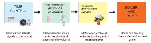
A) loss of igniter flame being constantly monitored by robust flame scanners. Essentially an interlock is a safety device to stop the boiler firing when various important parameters are not met. I have a diagram that shows the cylinder stat and the heating stat being wired to a three port motorized valve (y plan).
This is one of several variations. Then follow previous instructions shown in 4 and 5 above. Referring to the wiring diagram, figure 2 on page 8, the operating control and auxiliary limits 1, 2 and 3 will act as an operating control to recycle the burner.
At first i thought a boiler interlock was a wiring box but now i know it's a connection between the boiler controls. Use the d only on wiring diagram for d connection to. To get from 120 v to 24 v we use a transformer.
An interlock has been added which prevents burner operation unless the damper is in an open position. Wiring must be in strict compliance with csa c22.2 and nec/nfpa 70. This is fine if the boiler is 120 v.
Water (dripping, spraying, rain, etc.) during. If air conditioning is present, a temperature control should be Also you can look for the wiring diagram on one of the heating unit panels.
I would really love to share our actual interlock diagram implemented at the plant but let’s just make use of the standard extracted from the nfpa 85 document. Wiring must be in strict compliance with csa c22.2 and nec/nfpa 70. Wiring diagram for p/n 8200008 (forced air application) connect a wire from r on your existing thermostat to r on the additional thermostat then connect a wire from g on your existing thermostat to w on the additional thermostat.
I was going to on a previous post but negelected to do so untiol now. Ct 6, 10, 15 and 25 boiler wiring diagram. The aux start on delay timer starts.
Otherwise look on the web for the i/o manual for your model number of the propane heater. It’s best if you think about this yourself, using the various search engines to find out more about it. One more thing i feel the necessity to say.
This wiring diagram shows 120 v coming from l1 of a circuit breaker, through a switch, powering a boiler control and returning through l2, back to the neutral bar of the circuit breaker box. If new boiler will replace existing boiler, check for and correct system problems, such as: Whenever any of the auxiliary limits are
Brown/grey was the correct combination to the manual reset, which must be installed when boiler is off. Ct 35 and 50 boiler wiring diagram. Hrt 20 and 30 boiler wiring diagram.
Follow instruction for electrical wiring in boiler installation. Mph boiler without a burner wiring diagram. Here is a circuit diagram for a boiler interlock for a gravity system using tank and room thermostats.
Controller 4/ch to roomstat, then boiler and pump feeds connected together to the return from the roomstat. Please note that these drawings reflect the standard configuration. Trouble is i'm struggling to picture how they are wired.
• motorized damper is 4 cfm/ft2 (see table from ashrae standard ) california title 24 ( edition, section ) states that the dampers shall be certified in accordance with amca publication to have a maximum. Interlock each appliance to mechanical air supply system to prevent main Manufacturer shall be bell & gossett domestic pump, morton grove, il.
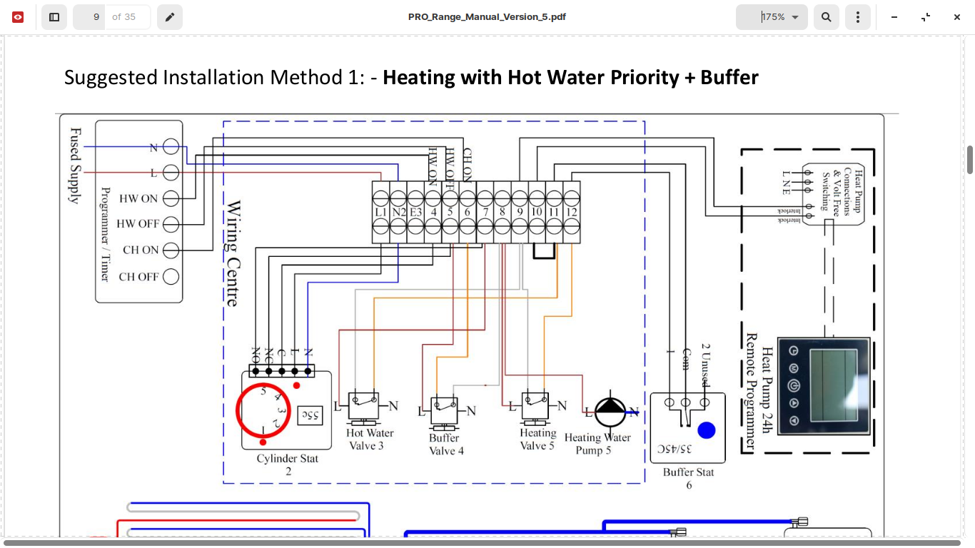
When a boiler is in demand, its aux relay will close, signaling the bas. When the valve has fully opened, its proof of open switch is made, closing the delayed interlock of the boiler — allowing the boiler to fire. You made another wiring diagram removing the interlock.
The bas opens the mov of the corresponding boiler. Keystone series boiler wiring diagram. To the circulator and connect only the relay or starter coil to boiler terminals.
Using the wiring diagram you supplied me: These interlocks depend on the complexity of the boiler con. A closed damper substantially reduces standby losses on boilers.
• this boiler shall be installed such that the gas ignition system components are protected from :
Whirlpool Cabrio Dryer Wiring Diagram Wiring Diagram
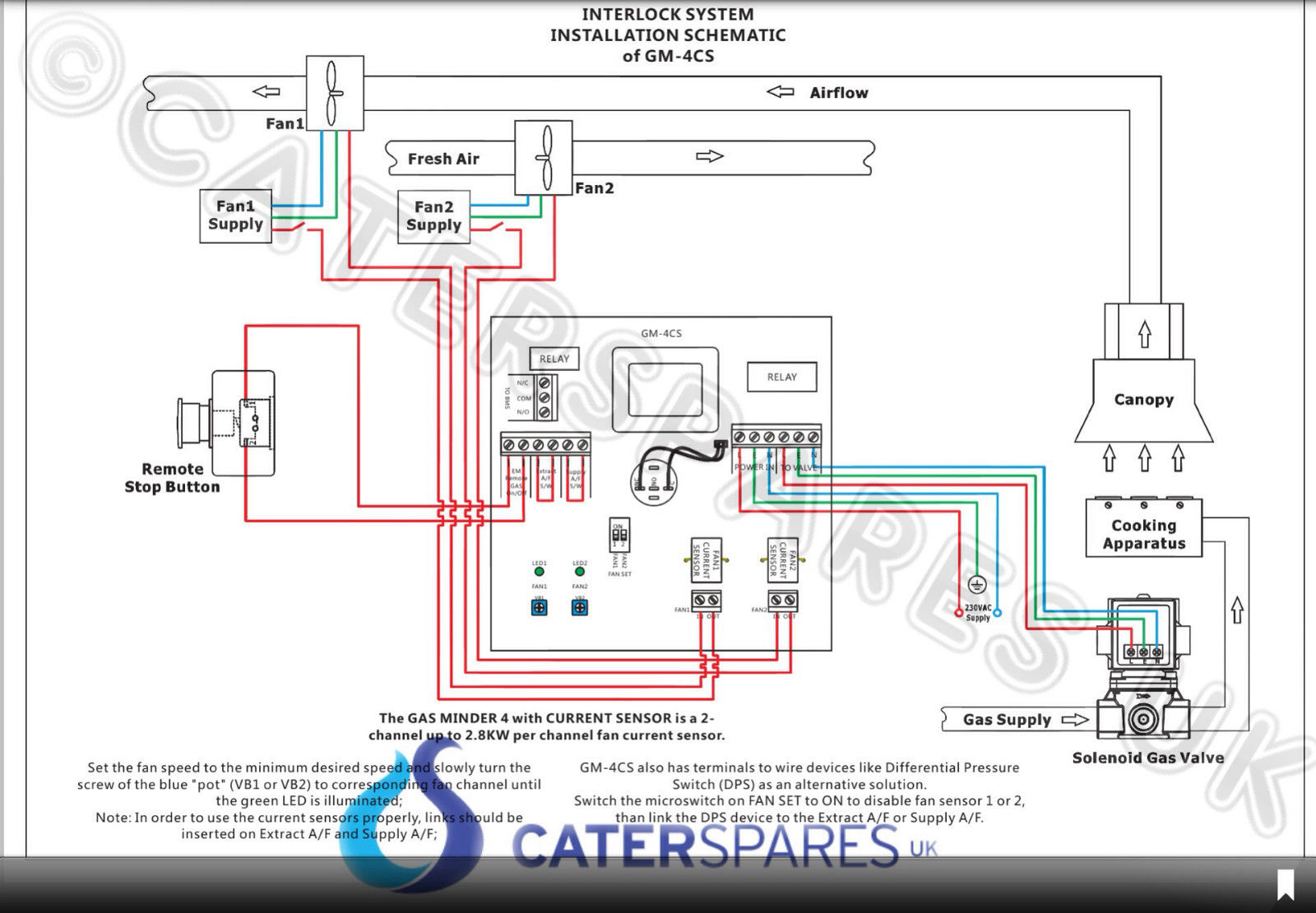
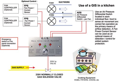
Gas Interlock Systems
Boiler Short Cycling
Cool Energy ASHPs'...............any good? Air Source Heat Pumps (ASHP)
NeoStat Smart Home Optimum Underfloor Heating

New Ignition Module, Wiring Question. — Heating Help The Wall
NeoStat Smart Home Optimum Underfloor Heating

COMMERCIAL GAS INTERLOCK SYSTEM CONTROL PANEL CURRENT MONITORING CONTROLLED UNIT CaterSparesUK
Baxi Boiler overheating!? DIYnot Forums
Goodman Furnace Thermostat Wiring

Redring Powerstream PSA12 ASCARI 12KW Electric Boiler Electric Central Heating Fastlec.co.uk

Billy needs a Y plan! Room stat; 3Port; Cylinder stat; Programmer ) Screwfix Community Forum

Gas Interlock System R and B Mechanical and Electrical
Boiler Air Lock Diagnosis Help InterNACHI Inspection Forum Boiler, Heating systems, Tech diy

Boiler System Airlock In Combi Boiler System

Wiring Diagram For 2 Zone Heating System And Hot Water Search Best 4K Wallpapers

Microwave Oven Wiring Diagram Safety Interlocks Repair YouTube

Programmable Touchscreen Thermostats Optimum Underfloor Heating

Exhaust Fan Interlock Wiring Diagram
